


A narrow ventilation shaft, a 334-step climb and a historic tilt – Building Design speaks to Stannah Lifts about the accessibility challenges overcome in the Elizabeth Tower’s ambitious restoration
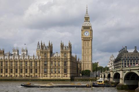
Throughout its 162 years, the Elizabeth Tower in Westminster has been subjected to weathering by the elements, heavy pollution, and bomb damage from the Second World War. Although several projects have been undertaken to clean and refurbish the tower, 2017 marked the beginning of the first complete restoration.
Sir Robert McAlpine Special Projects, which was appointed main contractor to restore the landmark, had to repair the building’s external fabric, renovate the clock, improve internal areas and oversee the installation of two lifts.
“Building a lift within a grade I-listed building is no simple task,” explains Dave Saunders, head of the major projects division at Stannah Lifts. “Modernisations must be as inconspicuous as possible, and the addition of new materials should not damage the existing historic fabric of the building.”
The project aimed to provide an energy-efficient and precisely engineered lift system that would ease the work of the clock engineers and could one day save lives in a medical emergency as an alternative to the 334 steps – all while preserving the clock tower’s historic environment.
>> Read: Technical Study: Elizabeth Tower refurbishment, London, by Purcell
Before 2017, the only way to reach the top of the tower was by walking up a narrow spiral stone staircase. The 334 steps posed a daunting deterrent for clock keepers, and the lack of lift access made it extremely challenging for maintenance teams to carry equipment and parts up to the belfry.
An existing ventilation shaft measuring just 4.9m x 2.4m ran from the base of the tower to the very top. The challenge was to design a lift that would fit into this narrow ventilation shaft, which had not been accessed since the tower’s original construction.
The teams also had to contend with the tower’s slight lean of 0.23° to the north-west. This means that the top of the tower is out of alignment by 0.22m, a crucial consideration for the design team.
The engineering of the lift project required close collaboration between Stannah, the lift supplier, and an independent lift consulting engineering firm, SVM Associates (SVMA).
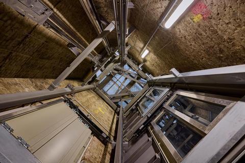
Within the 11.7m² ventilation shaft space, a bespoke energy-efficient, gearless, traction-drive passenger lift was built. “The lift is contained within its own structural skeleton to minimise any penetrations to the building’s historic fabric,” explains John Newbold, director at SVM Associates.
“The engineering interface between the new lift equipment and the existing features of the ventilation shaft, such as the original Victorian tie-rods, has been designed and installed with millimetre tolerance,” adds Saunders.
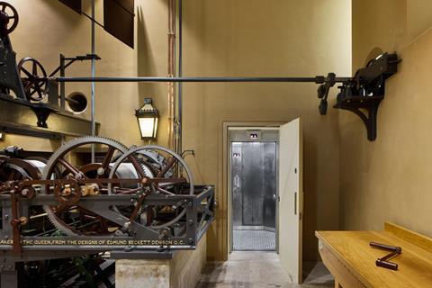
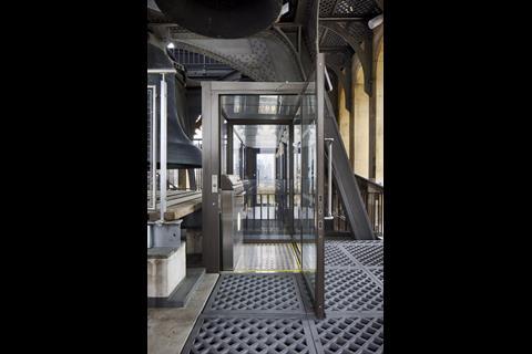
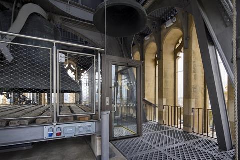
The tower’s physical constraints resulted in the main lift needing to stop two floors below the belfry. A smaller, 500kg hydraulic lift platform, accessed along a narrow corridor, then services the final 4.3m, providing access to the belfry.
“Due to the belfry environment, the lift has been built to an external specification with 316-grade stainless steel and hot-dipped galvanised steel, chequer plate floor and IP54-rated buttons,” says Newbold. “With a top speed of 1.5m/s, the main lift travels 57m from the ground to the ninth floor. The lift car has strengthened, hard-wearing walls and floors to ensure the lift can be used for maintenance goods as well as passengers.”
According to the design team, the horizontal ride quality of the lift meets the BCO Specification Guide’s requirements for passenger lifts. Furthermore, the lift drive machinery is located away from the top of the shaft so as not to disrupt the BBC’s live recording of Big Ben’s chimes.
The 13-person passenger lift has been designed with several energy-efficient features. The regenerative drive acts as a generator whenever gravity assists the lift, returning power to the mains. The counterweight’s mass is optimised to match the likely load in the lift car, thereby saving energy, and when the lift is idle, it turns off its non-essential power loads. The pulley ropes are made from polymer rather than steel, so they are lighter and have less inertia, making them easier to spin. Lastly, the lift is driven directly by a motor without a traditional gearbox, reducing power losses from mechanical inefficiency.
Additionally, the lift incorporates the required accessibility features, including controls, dimensions and audiovisual passenger information. Dual power supplies to the lift enable passengers to vacate safely if required, even if the mains power is cut off.
As for maintenance, the lift’s machinery is housed in a conventional motor room, enabling maintenance personnel to access the machine and control equipment safely. Mechanical systems, such as machines, pulleys and compensation systems, are said to be virtually maintenance-free. Individual rope tension is monitored by electronic transducers, and service engineers are notified when rope adjustment is required. The control system is also equipped to regularly report its status and performance to a remote monitoring system.
Nick Sturge, project manager at Sir Robert McAlpine Special Projects, says: “The installation of the lifts in the Elizabeth Tower restoration project has been a true feat of precision engineering and ingenuity. This project was enhanced by the diversity of skills and trades that made it possible and had a clear focus on sustainability, championing the use of energy-efficient technologies.”


No comments yet